In my last post I introduced some of the project I’ve been working on. This post is a little more technical; if you don’t care, and just want to see a 91 megapixel image from inside Hive13, skip to the end.
Those of you who thought a little further on the first post might have seen that I made an apparatus that captures a series of images from fairly precise positions, and then completely discards that position information, hands the images off to Hugin and PanoTools, and has them crunch numbers for awhile to calculate the very same position information for each image.
That’s a slight oversimplification - they also calculate lens parameters, they calculate other position parameters that I ignore, and the position information will deviate because:
- Stepper motors can stall, and these steppers may have some hysteresis in the gears.
- The pan and tilt axes aren’t perfectly perpendicular.
- The camera might have a slight tilt or roll to it due to being built that way, due to the sensor being mounted that way, or due to the whole assembly being mounted that way.
- The camera’s entrance pupil may not lie exactly at the center of the two axes, which will cause rotations to also produce shifts in position that they must account for. (No, it’s not the nodal point. No, it’s not the principal point. More on this will follow later. Those shifts in position can also cause parallaxing, which is much more annoying to account for. To get what I mean, close one eye and look at a stationary item in the foreground, and then try to rotate your head without the background moving behind it.)
That is, the position information we have is subject to inaccuracies, and is not sufficient on its own. However, these tools still do a big numerical optimization, and a starting position that is “close” can help them along, so we may as well use the information.
Also, these optimizations depend on having enough good data to average out to a good answer. Said data comes from matches between features in overlapping images, say, using something like SIFT and RANSAC. Even if we’ve left plenty of overlap in the images we’ve shot, some parts of scenes can simply lack features like corners that work well for this (see chapter 4 of Computer Vision: Algorithms and Applications if you’re really curious). We may end up with images for which optimization can’t really improve the estimated position, and here a guess based on where we think the stepper motors were is much better than nothing.
If we look at the PTO file format (which Hugin & PanoTools use) in its i-lines section, it has pitch, yaw, and roll for each image. Pitch and yaw are precisely the axes in which the steppers move the camera (recall the pictures of the rig from the last post); the roll axis is how the camera has been rotated. We need to know the lens’s angle of view too, but as with other parameters it’s okay to just guess and let the optimization fine-tune it. The nominal focal length probably won’t be exact anyhow.
Helpfully, PanoTools provides tools like pto_gen and pto_var,
and I use these in my script to generate a basic .pto file from the
2D grid in which I shot images. All that’s needed is to add up the
steps taken to reach each shot, convert steps to degrees, which for
these steppers means using 360 / 64 / 63.63895 = about 0.0884
(according to this), and making sure that the positive and
negative degrees correspond to the right direction in each axis.
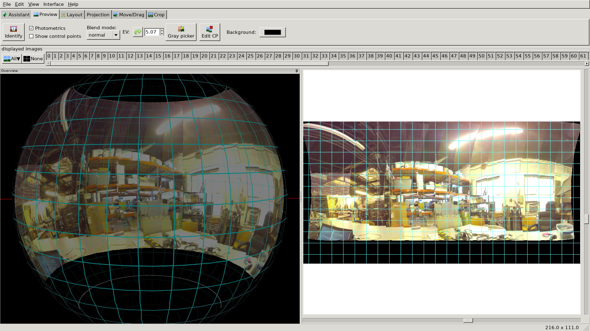
With no refining, tweaking, or optimization, only the per-image stepper motor positions and my guess at the lens’s FOV, here is how this looks in Hugin’s fast preview:
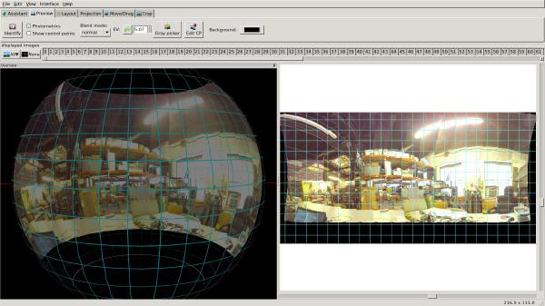
(This is a test run that I did inside of Hive13, by the way. I used the CS-mount ArduCam and its included lens. Shots were in a 14 x 4 grid and about 15 degrees apart. People and objects were moving around inside the space at the time, which may account for some weirdness…)
Though it certainly has gaps and seams, it’s surprisingly coherent. The curved-lines distortion in Hugin’s GUI on the right is due to the projection, and perfect optics and perfect positioning information can’t correct it. Do you recall learning in school that it’s impossible to put the globe of the world into a flat two-dimensional map without distortion? This is exactly the same problem - which is likely why Hugin’s GUI shows all the pictures mapped onto a globe on the left. That’s another topic completely though…
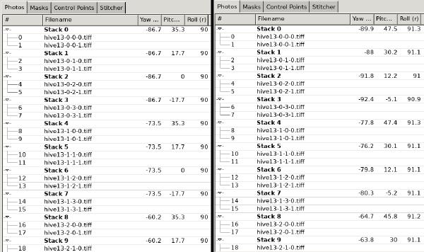
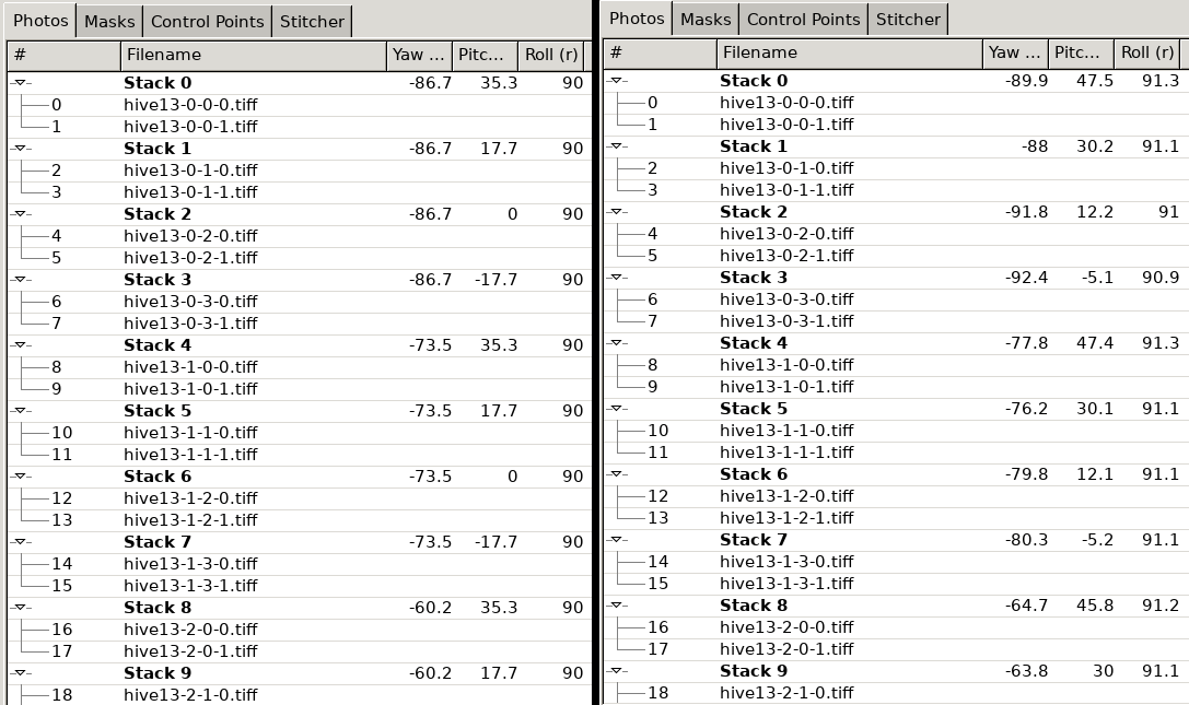
Of course, Hugin pretty much automates the process of finding control points, matching them, and then finding optimal positions for each image, so that is what I did next. We can also look at these positions directly in Hugin’s GUI. The image below contains two screenshots - on the left, the image positions from the stepper motors, and on the right, the optimized positions that Hugin calculated:
They sort of match up, though pitch deviates a bit. I believe that’s because I shifted the pitch of the entire thing to straighten it out, or perhaps Hugin did this automatically to center it, but I haven’t examined this in detail yet. (Helpfully, the same process can be used to calibrate lenses and compute the real focal length at the same time - which can be particularly necessary for cases like this where I’m trying to get the most out of cheap optics and when the Exif tags won’t include focal lengths.)
Result
A full-resolution JPEG of the result after automated stitching, exposure fusion, lens correction, and so on, is below in this handy zoomable viewer using OpenSeadragon:
It’s 91.5 megapixels; if the above viewer doesn’t work right, a full-resolution JPEG is available too. The full TIFF image is 500 MB, so understandably, I didn’t feel like hosting it, particularly when it’s not the prettiest photo or the most technically-perfect one (it’s full of lens flare, chromatic aberration, overexposure, sensor noise, and the occasional stitching artifact).
However, you can look up close and see how well the details came through - which I find quite impressive for cheap optics and a cheap sensor.
Part 3 delves into the image processing workflow.